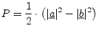
Voltage and current are hard to measure at high frequencies. Short
and open circuits (used by definitions of most n-port parameters) are
hard to realize at high frequencies. Therefore, microwave engineers
work with so-called scattering parameters (S parameters), that uses
waves and matched terminations (normally ![]() ). This procedure
also minimizes reflection problems.
). This procedure
also minimizes reflection problems.
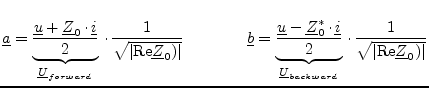
A (normalized) wave is defined as ingoing wave
![]() or
outgoing wave
or
outgoing wave
![]() :
:
| (1.2) |
 |
(1.3) |
 |
(1.4) |
One final note: The reference impedance
![]() can be
arbitrary chosen. It normally is real, and there is no urgent
reason to use a complex one. The definitions in equation
1.1, however, are made form complex impedances. These
ones stem from [1], where they are named "power waves".
These power waves are a useful way to define waves with complex
reference impedances, but they differ from the waves introduced
in the following chapter. For real reference impedances both
definitions equal each other.
can be
arbitrary chosen. It normally is real, and there is no urgent
reason to use a complex one. The definitions in equation
1.1, however, are made form complex impedances. These
ones stem from [1], where they are named "power waves".
These power waves are a useful way to define waves with complex
reference impedances, but they differ from the waves introduced
in the following chapter. For real reference impedances both
definitions equal each other.