 |
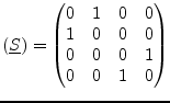
(9.144) |
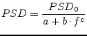
To implement the frequency dependencies of all common noise PSDs the following equation can be used.
|
(9.144) |
Where ![]() is frequency and
is frequency and ![]() ,
, ![]() ,
, ![]() are the parameters. The
following PSDs appear in electric devices.
are the parameters. The
following PSDs appear in electric devices.
| white noise (thermal noise, shot noise): | |
| pink noise (flicker noise): | |
| Lorentzian PSD (generation-recombination noise): |
Noise current source with a current power spectral density of ![]() :
:
 |
(9.145) |
The MNA matrix entries for DC and AC analysis are all zero.
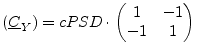
The noise wave correlation matrix of a noise current source with
current power spectral density ![]() and its S parameter matrix
write as follows.
and its S parameter matrix
write as follows.
 |
(9.146) |
A noise voltage source (voltage power spectral density ![]() ) cannot
be modeled with the noise current matrix. That is why one has to use
a noise current source (current power spectral density
) cannot
be modeled with the noise current matrix. That is why one has to use
a noise current source (current power spectral density ![]() )
connected to a gyrator (transimpedance
)
connected to a gyrator (transimpedance ![]() ) satisfying the equation
) satisfying the equation
| (9.147) |
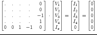
Figure 9.7 shows an example.
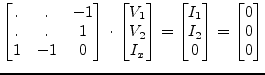
The MNA matrix entries of the above construct (gyrator ratio ![]() ) is
similiar to a voltage source with zero voltage.
) is
similiar to a voltage source with zero voltage.
 |
(9.148) |
The appropriate noise current correlation matrix yields:
 |
(9.149) |
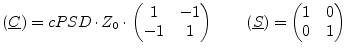
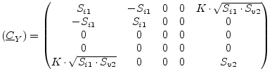
The noise wave correlation matrix of a noise voltage source with
voltage power spectral density ![]() and its S parameter matrix
write as follows.
and its S parameter matrix
write as follows.
 |
(9.150) |
For two correlated noise current sources the (normalized) correlation
coefficient ![]() must be known (with
must be known (with
![]() ). If the first
noise source has the current power spectral
density
). If the first
noise source has the current power spectral
density ![]() and is connected to node 1 and 2, and if furthermore
the second noise source has the spectral density
and is connected to node 1 and 2, and if furthermore
the second noise source has the spectral density ![]() and is connected
to node 3 and 4, then the correlation matrix writes:
and is connected
to node 3 and 4, then the correlation matrix writes:
 |
(9.151) |
The MNA matrix entries for DC and AC analysis are all zero.
The noise wave correlation matrix of two correlated noise current
sources with current power spectral densities ![]() and
and ![]() and correlation coefficient
and correlation coefficient ![]() writes as follows.
writes as follows.
 |
(9.152) |
 |
(9.153) |
For two correlated noise voltage sources two extra rows and columns are needed in the MNA matrix:
 |
(9.154) |
The appropriate noise current correlation matrix (with the noise
voltage power spectral densities ![]() and
and ![]() and the
correlation coefficient
and the
correlation coefficient ![]() ) yields:
) yields:
 |
(9.155) |
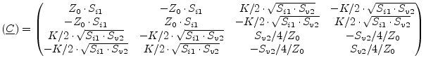
The noise wave correlation matrix of two correlated noise voltage
sources with voltage power spectral densities ![]() and
and ![]() and correlation coefficient
and correlation coefficient ![]() and its S parameter matrix write as
follows.
and its S parameter matrix write as
follows.
 |
(9.156) |
 |
(9.157) |
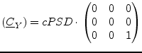
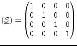
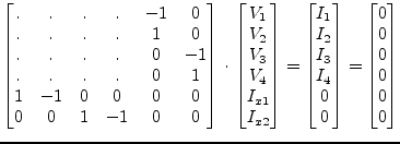
If a noise current source (ports 1 and 2) and a noise voltage source (ports 3 and 4) are correlated, the MNA matrix entries are as follows.
 |
(9.158) |
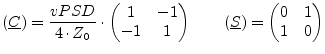
The appropriate noise current correlation matrix (with the noise
power spectral densities ![]() and
and ![]() and the
correlation coefficient
and the
correlation coefficient ![]() ) yields:
) yields:
 |
(9.159) |
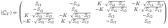
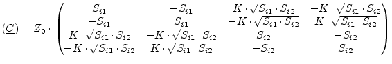
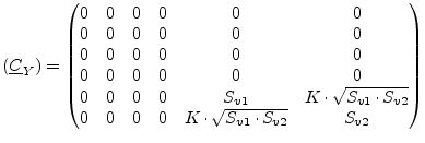
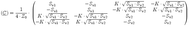
The noise wave correlation matrix of one correlated noise current
source ![]() and one noise voltage source
and one noise voltage source ![]() with
correlation coefficient
with
correlation coefficient ![]() writes as follows.
writes as follows.
 |
(9.160) |
 |
(9.161) |
![\includegraphics[width=9cm]{Unoise}](img1078.png)