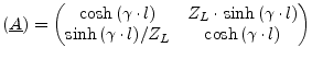
A transmission line is usually described by its ABCD-matrix. (Note
that in ABCD-matrices, i.e. the chain matrix representation, the
current ![]() is defined to flow out of the output port.)
is defined to flow out of the output port.)
These can easily be recalculated into impedance parameters.
 |
(9.194) | |
 |
(9.195) |
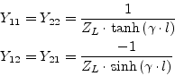
Or in admittance parameter representation it yields
whence ![]() denotes the propagation constant
denotes the propagation constant
![]() and
and
![]() is the length of the transmission line.
is the length of the transmission line. ![]() represents the
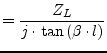
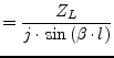
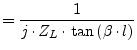
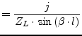
characteristic impedance of the transmission line. The Y-parameters
as defined by eq. (9.199) can be used for the microstrip
line. For an ideal, i.e. lossless, transmission lines they write
accordingly.
represents the
characteristic impedance of the transmission line. The Y-parameters
as defined by eq. (9.199) can be used for the microstrip
line. For an ideal, i.e. lossless, transmission lines they write
accordingly.
 |
(9.197) | |
 |
(9.198) | |
 |
(9.199) | |
 |
(9.200) |
The scattering matrix of an ideal, lossless transmission line with
impedance ![]() and electrical length
and electrical length ![]() writes as follows.
writes as follows.
 |
(9.201) |
 |
(9.202) |
 |
(9.203) |
With ![]() = 299 792 458 m/s being the vacuum light velocity.
Adding attenuation to the transmission line, the quantity
= 299 792 458 m/s being the vacuum light velocity.
Adding attenuation to the transmission line, the quantity ![]() extends to:
extends to:
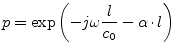 |
(9.204) |
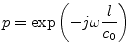
Another equivalent equation set for the calculation of the
scattering parameters is the following:
With the physical length ![]() of the component, its impedance
of the component, its impedance
![]() and propagation constant
and propagation constant ![]() , the complex propagation
constant
, the complex propagation
constant ![]() is given by
is given by
| (9.205) |
where ![]() is the attenuation factor and
is the attenuation factor and ![]() is the (real)
propagation constant given by
is the (real)
propagation constant given by
| (9.206) |
where
![]() is the effective dielectric
constant and
is the effective dielectric
constant and ![]() is the TEM propagation constant
is the TEM propagation constant ![]() for the
equivalent transmission line with an air dielectric.
for the
equivalent transmission line with an air dielectric.
| (9.207) |
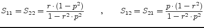
The expressions used to calculate the scattering parameters are given by
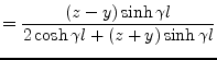 |
(9.208) | |
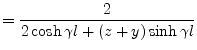 |
(9.209) |
with ![]() being the normalized impedance and
being the normalized impedance and ![]() is the normalized
admittance.
is the normalized
admittance.