![\includegraphics[width=0.35\linewidth]{coax}](img2519.png)
|
The characteristic impedance of a coaxial line can be calculated as follows:
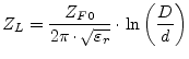 |
(13.1) |
Overall losses in a coaxial cable consist of dielectric and conductor losses. The dielectric losses compute as follows:
| (13.2) |
The conductor (i.e. ohmic) losses are specified by
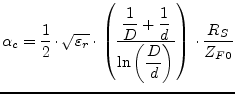 |
(13.3) |
with ![]() denoting the sheet resistance of the conductor material,
i.e. the skin resistance
denoting the sheet resistance of the conductor material,
i.e. the skin resistance
| (13.4) |
In normal operation a signal wave passes through the coaxial line as a TEM wave with no electrical or magnetic field component in the direction of propagation. Beyond a certain cutoff frequency additional (unwanted) higher order modes are excited.
| (13.5) | ||
| (13.6) |