One of the most common tasks in microwave technologies is to extract a frequency band from others. Optimized filters exist in order to easily create a filter with an appropriate characteristic. The most popular ones are:
| Name | Property |
| Bessel filter (Thomson filter) | as constant group delay as possible |
| Butterworth filter (power-term filter) | as constant amplitude transfer function as possible |
| Chebychev filter type I | constant ripple in pass band |
| Chebychev filter type II | constant ripple in stop band |
| Cauer filter (elliptical filter) | constant ripple in pass and stop band |
From top to bottom the following properties increase:
The order ![]() of a filter denotes the number of poles of its (voltage)
transfer function. It is:
of a filter denotes the number of poles of its (voltage)
transfer function. It is:
| slope of asymptote |
(14.11) |
The best possibility to realize a filters in VHF and UHF bands are LC ladder filters. The usual way to synthesize them is to first calculate a low-pass (LP) filter and afterwards transform it into a high-pass (HP), band-pass (BP) or band-stop (BS) filter. To do so, each component must be transformed into another.
In a low-pass filter, there are parallel capacitors ![]() and
series inductors
and
series inductors ![]() in alternating order. The other filter
classes can be derived from it:
in alternating order. The other filter
classes can be derived from it:
In a high-pass filter:
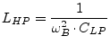 |
(14.12) | |
 |
(14.13) |
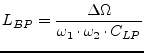
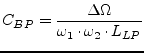
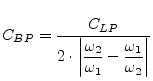
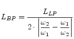
In a band-pass filter:
| parallel resonance circuit with | (14.14) | |
 |
(14.15) | |
 |
(14.16) | |
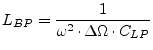
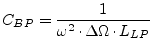
| series resonance circuit with | (14.17) | |
 |
(14.18) | |
 |
(14.19) |
In a band-stop filter:
| series resonance circuit with | (14.20) | |
 |
(14.21) | |
 |
(14.22) | |
| parallel resonance circuit with | (14.23) | |
 |
(14.24) | |
 |
(14.25) |
Where
| lower corner frequency of frequency band | (14.26) | |
| upper corner frequency of frequency band | (14.27) | |
| center frequency of frequency band |
(14.28) | |
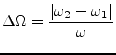 |
(14.29) |
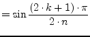
The ![]() -th element of an
-th element of an ![]() order Butterworth low-pass ladder filter is:
order Butterworth low-pass ladder filter is:
| capacitance: |
(14.30) | |||
| inductance: |
(14.31) | |||
| with |
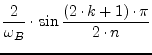 |
(14.32) |
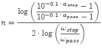
The order of the Butterworth filter is dependent on the specifications provided by the user. These specifications include the edge frequencies and gains.
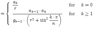
The equations for a Chebyshev type I filter are defined recursivly.
With ![]() being the passband ripple in decibel, the
being the passband ripple in decibel, the ![]() -th
element of an
-th
element of an ![]() order low-pass ladder filter is:
order low-pass ladder filter is:
| capacitance: |
(14.34) | |||
| inductance: |
(14.35) | |||
| with |
 |
(14.36) | ||
 |
(14.37) | |||
 |
(14.38) | |||
 |
(14.39) | |||
|
(14.40) |
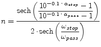
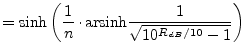
The order of the Chebychev filter is dependent on the specifications provided by the user. The general form of the calculation for the order is the same as for the Butterworth, except that the inverse hyperbolic cosine function is used in place of the common logarithm function.
Because of the nature of the derivation of the inverse Chebychev approxiation function from the standard Chebychev approximation the calculation of the order (14.41) is the same.